Geometry module
The ACTS geometry model is strongly based on the ATLAS Tracking geometry. Its core is built on a surface-based description that make up all geometry objects of higher complexity. This design has been chosen as the surface objects can be used together with the track propagation module and thus all geometry objects become natively integrated into the tracking software.
Note
There is an ongoing rewrite of the geometry and navigation modules where logical layers will be modelled as volumes, see Experimental Geometry module.
GeometryObject base class
All geometry objects in Acts inherit from a virtual Acts::GeometryObject base class.
-
class GeometryObject
Base class to provide GeometryIdentifier interface:
simple set and get
It also provides the binningPosition method for Geometry geometrical object to be binned in BinnedArrays
Subclassed by Acts::Layer, Acts::Surface, Acts::Volume
Public Functions
-
GeometryObject() = default
Defaulted constructor.
-
inline GeometryObject(const GeometryIdentifier &geometryId)
Constructor from a value.
- Parameters
geometryId – the geometry identifier of the object
-
GeometryObject(const GeometryObject&) = default
Defaulted copy constructor.
-
inline void assignGeometryId(const GeometryIdentifier &geometryId)
Set the value.
- Parameters
geometryId – the geometry identifier to be assigned
-
virtual Vector3 binningPosition(const GeometryContext &gctx, BinningValue bValue) const = 0
Force a binning position method.
- Parameters
gctx – The current geometry context object, e.g. alignment
bValue – is the value in which you want to bin
- Returns
vector 3D used for the binning schema
-
inline virtual double binningPositionValue(const GeometryContext &gctx, BinningValue bValue) const
Implement the binningValue.
- Parameters
gctx – The current geometry context object, e.g. alignment
bValue – is the dobule in which you want to bin
- Returns
float to be used for the binning schema
-
inline const GeometryIdentifier &geometryId() const
- Returns
the geometry id by reference
-
inline GeometryObject &operator=(const GeometryObject &geometryId)
Assignment operator.
- Parameters
geometryId – the source geometryId
Note
The binningPosition(const GeometryContext& gctx, BinningValue& bVal) method allows to define
a customized position of this object when being subject to ordering in some specific binnings, e.g. in a BinnedArray or a SurfaceArray.
This class ensures that a unique Acts::GeometryIdentifier is assigned to every geometry
object.
Geometry identifier
The Acts::GeometryIdentifier is mainly used for fast identification of the type of
the geometry object (as most of them are either extensions or containers of the
Acts::Surface objects) and for the identification of the geometry surfaces after
building, e.g. for the uploading/assigning of material to the surface after
creation. The Acts::GeometryIdentifier uses a simple masking procedure for applying an
identification schema.
While it is used in Acts-internal applications such as material mapping, it is not employed for
EventData and Geometry identification in an experiment setup. Instead, one should define and use the
Identifier class in the latter case.
-
class GeometryIdentifier
Identifier for geometry nodes within the geometry hierarchy.
An identifier can be split into the following components. They define a hierarchy of objects starting from the high-level volumes:
Volume
Boundary surfaces (for a volume)
Layers (confined within a volume)
Approach surfaces (for a layer)
Sensitive surfaces (confined to a layer, also called modules)
Private Static Attributes
-
static constexpr Value kApproachMask = 0x0000000ff0000000
(2^8)-1 = 255 approach surfaces
-
static constexpr Value kBoundaryMask = 0x00ff000000000000
(2^8)-1 = 255 boundaries
-
static constexpr Value kExtraMask = 0x00000000000000ff
(2^8)-1 = 255 extra values
-
static constexpr Value kLayerMask = 0x0000fff000000000
(2^12)-1 = 4095 layers
-
static constexpr Value kSensitiveMask = 0x000000000fffff00
(2^20)-1 = 1048575 sensitive surfaces
-
static constexpr Value kVolumeMask = 0xff00000000000000
(2^8)-1 = 255 volumes
Surface classes
All classes which represent a thin surface in ACTS inherit from
the common virtual base class Acts::Surface, which defines
the public interface of all surfaces. While the different concrete
surface classes are defined by their respective native local
coordinate system, the shapes on these surfaces are defined by classes
that inherit from Acts::SurfaceBounds, which every surface must provide.
In case of boundless surfaces, a special Acts::InfiniteBounds class is
available.
Each Acts::Surface instance reports its type from Acts::Surface::type():
-
enum Acts::Surface::SurfaceType
This enumerator simplifies the persistency & calculations, by saving a dynamic_cast, e.g.
for persistency
Values:
-
enumerator Cone
-
enumerator Cylinder
-
enumerator Disc
-
enumerator Perigee
-
enumerator Plane
-
enumerator Straw
-
enumerator Curvilinear
-
enumerator Other
-
enumerator Cone
Surface Type |
Local Coordinates |
Bound Types available |
|---|---|---|
\([r\phi, z]\) |
||
\([r, \phi]\) |
||
\([r, \phi]\) |
|
|
\([x, y]\) |
|
|
\([d, z]\) |
||
\([d_0, z_0]\) |
Tip
In an ideal setup, the coordinate systems also define the readout measurement directions. In such a case, a track prediction from the propagation will already be in the correct frame of the measurement and residual or compatibility checks will not need additional coordinate transformations.
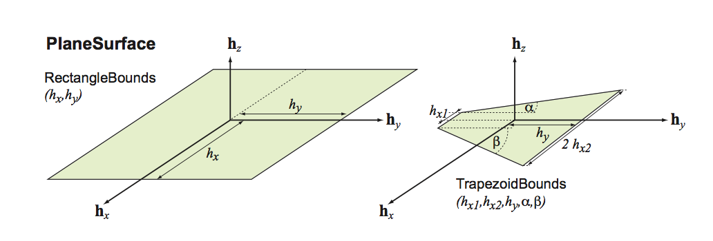
Plane surface
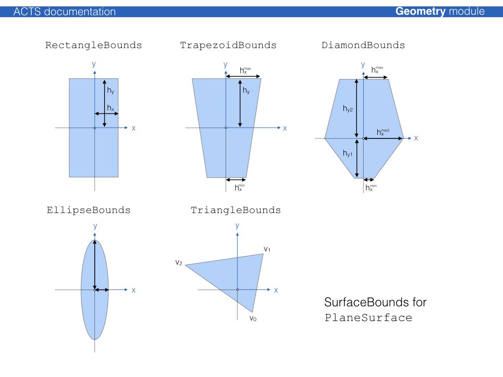
-
class PlaneSurface : public Acts::Surface
Class for a planaer in the TrackingGeometry.
The PlaneSurface extends the Surface class with the possibility to convert local to global positions (vice versa).
Subclassed by Acts::PlaneLayer
Public Functions
-
virtual Result<Vector2> globalToLocal(const GeometryContext &gctx, const Vector3 &position, const Vector3 &direction, double tolerance = s_onSurfaceTolerance) const override
Global to local transformation.
Note
For planar surfaces the momentum direction is ignored in the global to local transformation
- Parameters
gctx – The current geometry context object, e.g. alignment
position – global 3D position - considered to be on surface but not inside bounds (check is done)
direction – global 3D momentum direction (optionally ignored) method symmetry)
tolerance – optional tolerance within which a point is considered valid on surface
- Returns
a Result<Vector2> which can be !ok() if the operation fails
-
virtual SurfaceIntersection intersect(const GeometryContext &gctx, const Vector3 &position, const Vector3 &direction, const BoundaryCheck &bcheck = false, ActsScalar tolerance = s_onSurfaceTolerance) const final
Straight line intersection.
mathematical motivation:
the equation of the plane is given by: \( \vec n \cdot \vec x = \vec n \cdot \vec p,\) where \( \vec n = (n_{x}, n_{y}, n_{z})\) denotes the normal vector of the plane, \( \vec p = (p_{x}, p_{y}, p_{z})\) one specific point on the plane and \( \vec x = (x,y,z) \) all possible points on the plane.
Given a line with:\( \vec l(u) = \vec l_{1} + u \cdot \vec v \)
,
the solution for
\( u \) can be written: \( u = \frac{\vec n (\vec p - \vec l_{1})}{\vec n \vec v}\) If the denominator is 0 then the line lies:either in the plane
perpendicular to the normal of the plane
Note
expected to be normalized)
- Parameters
gctx – The current geometry context object, e.g. alignment
position – The start position of the intersection attempt
direction – The direction of the intersection attempt, (
bcheck – The boundary check directive
tolerance – the tolerance used for the intersection
- Returns
the SurfaceIntersection object
-
virtual Vector3 localToGlobal(const GeometryContext &gctx, const Vector2 &lposition, const Vector3 &direction) const override
Local to global transformation.
Note
For planar surfaces the momentum direction is ignored in the local to global transformation
- Parameters
gctx – The current geometry context object, e.g. alignment
lposition – local 2D position in specialized surface frame
direction – global 3D momentum direction (optionally ignored)
- Returns
the global position by value
-
inline Vector3 normal(const GeometryContext &gctx) const
Normal vector return without argument.
-
virtual Vector3 normal(const GeometryContext &gctx, const Vector2 &lposition) const final
Normal vector return.
return a Vector3 by value
- Parameters
gctx – The current geometry context object, e.g. alignment
lposition – is the local position is ignored
-
Vector3 normal(const GeometryContext &gctx, const Vector2 &lposition) const = 0
Normal vector return without argument.
-
Vector3 normal(const GeometryContext &gctx, const Vector3 &position) const
Normal vector return without argument.
-
virtual Result<Vector2> globalToLocal(const GeometryContext &gctx, const Vector3 &position, const Vector3 &direction, double tolerance = s_onSurfaceTolerance) const override
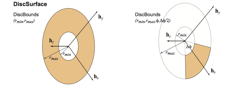
Disc surface
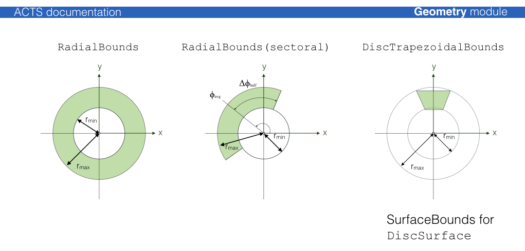
-
class DiscSurface : public Acts::Surface
Class for a disc surface (or a segment thereof)
The DiscSurface is defined by the local polar coordinates \( (r,phi) \).
The surface transform positions the disc such that the origin is at \( r=0 \), independent of the provided
DiscBounds. The normal vector of the disc (i.e., the local \(z\)-axis) is given by \( \vec e_{z} = \vec e_{r} \times\vec e_{phi} \).The disc surface The only surface type for which the covariance matrix is NOT given in the reference frame. A conversion from polar to cartesian coordinates needs to happen to transfer the local coordinates onto the cartesian reference frame coordinates.
Subclassed by Acts::DiscLayer
Public Functions
-
virtual Result<Vector2> globalToLocal(const GeometryContext &gctx, const Vector3 &position, const Vector3 &direction, double tolerance = s_onSurfaceTolerance) const final
Global to local transformation.
Note
the direction is ignored for Disc surfaces in this calculateion
- Parameters
gctx – The current geometry context object, e.g. alignment
position – global 3D position - considered to be on surface but not inside bounds (check is done)
direction – global 3D momentum direction (optionally ignored)
tolerance – optional tolerance within which a point is considered valid on surface
- Returns
a Result<Vector2> which can be !ok() if the operation fails
-
virtual SurfaceIntersection intersect(const GeometryContext &gctx, const Vector3 &position, const Vector3 &direction, const BoundaryCheck &bcheck = false, ActsScalar tolerance = s_onSurfaceTolerance) const final
Straight line intersection schema.
Mathematical motivation:
the equation of the plane is given by: \( \vec n \cdot \vec x = \vec n \cdot \vec p,\) where \( \vec n = (n_{x}, n_{y}, n_{z})\) denotes the normal vector of the plane, \( \vec p = (p_{x}, p_{y}, p_{z})\) one specific point on the plane and \( \vec x = (x,y,z) \)
all possible points on the plane.
Given a line with:
\( \vec l(u) = \vec l_{1} + u \cdot \vec v \),
the solution for
\( u \) can be written: \( u = \frac{\vec n (\vec p - \vec l_{1})}{\vec n \vec v}\) If the denominator is 0 then the line lies:either in the plane
perpendicular to the normal of the plane
Note
expected to be normalized (no checking)
- Parameters
gctx – The current geometry context object, e.g. alignment
position – The global position as a starting point
direction – The global direction at the starting point
bcheck – The boundary check prescription
tolerance – the tolerance used for the intersection
- Returns
The SurfaceIntersection object
-
virtual Vector3 localToGlobal(const GeometryContext &gctx, const Vector2 &lposition, const Vector3 &direction) const final
Local to global transformation For planar surfaces the momentum direction is ignored in the local to global transformation.
- Parameters
gctx – The current geometry context object, e.g. alignment
lposition – local 2D position in specialized surface frame
direction – global 3D momentum direction (optionally ignored)
- Returns
global position by value
-
inline Vector3 normal(const GeometryContext &gctx) const
Normal vector return without argument.
-
virtual Vector3 normal(const GeometryContext &gctx, const Vector2 &lposition) const final
Normal vector return.
- Parameters
gctx – The current geometry context object, e.g. alignment
lposition – The local position is ignored
- Returns
a Vector3 by value
-
Vector3 normal(const GeometryContext &gctx, const Vector2 &lposition) const = 0
Normal vector return without argument.
-
Vector3 normal(const GeometryContext &gctx, const Vector3 &position) const
Normal vector return without argument.
-
virtual Result<Vector2> globalToLocal(const GeometryContext &gctx, const Vector3 &position, const Vector3 &direction, double tolerance = s_onSurfaceTolerance) const final
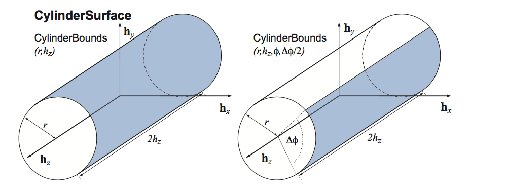
Cylinder surface
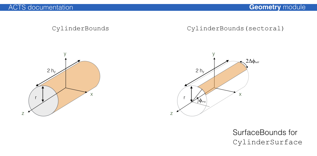
-
class CylinderSurface : public Acts::Surface
Class for a CylinderSurface in the TrackingGeometry.
It inherits from Surface.
The cylinder surface has a special role in the TrackingGeometry, since it builds the surfaces of all TrackingVolumes at container level for a cylindrical tracking geometry.
Subclassed by Acts::CylinderLayer
Public Functions
-
virtual Result<Vector2> globalToLocal(const GeometryContext &gctx, const Vector3 &position, const Vector3 &direction, double tolerance = s_onSurfaceTolerance) const final
Global to local transformation.
- Parameters
gctx – The current geometry context object, e.g. alignment
position – is the global position to be transformed
direction – is the global momentum direction (ignored in this operation)
tolerance – optional tolerance within which a point is considered valid on surface
- Returns
a Result<Vector2> which can be !ok() if the operation fails
-
virtual SurfaceIntersection intersect(const GeometryContext &gctx, const Vector3 &position, const Vector3 &direction, const BoundaryCheck &bcheck = false, ActsScalar tolerance = s_onSurfaceTolerance) const final
Straight line intersection schema from position/direction.
If possible returns both solutions for the cylinder
- Parameters
gctx – The current geometry context object, e.g. alignment
position – The position to start from
direction – The direction at start
bcheck – the Boundary Check
tolerance – the tolerance used for the intersection
- Returns
SurfaceIntersection object (contains intersection & surface)
-
virtual Vector3 localToGlobal(const GeometryContext &gctx, const Vector2 &lposition, const Vector3 &direction) const final
Local to global transformation.
- Parameters
gctx – The current geometry context object, e.g. alignment
lposition – is the local position to be transformed
direction – is the global momentum direction (ignored in this operation)
- Returns
The global position by value
-
inline Vector3 normal(const GeometryContext &gctx) const
Normal vector return without argument.
-
virtual Vector3 normal(const GeometryContext &gctx, const Vector2 &lposition) const final
Return method for surface normal information.
Note
for a Cylinder a local position is always required for the normal vector
- Parameters
gctx – The current geometry context object, e.g. alignment
lposition – is the local position for which the normal vector is requested
- Returns
normal vector at the local position by value
-
Vector3 normal(const GeometryContext &gctx, const Vector2 &lposition) const = 0
Normal vector return without argument.
-
Vector3 normal(const GeometryContext &gctx, const Vector3 &position) const
Normal vector return without argument.
-
virtual Vector3 normal(const GeometryContext &gctx, const Vector3 &position) const final
Return method for surface normal information.
Note
for a Cylinder a local position is always required for the normal vector
- Parameters
gctx – The current geometry context object, e.g. alignment
position – is the global position for which the normal vector is requested
- Returns
normal vector at the global position by value
-
virtual Result<Vector2> globalToLocal(const GeometryContext &gctx, const Vector3 &position, const Vector3 &direction, double tolerance = s_onSurfaceTolerance) const final
Cone surface
-
class ConeSurface : public Acts::Surface
Class for a conical surface in the Tracking geometry.
It inherits from Surface.
The ConeSurface is special since no corresponding Track parameters exist since they’re numerical instable at the tip of the cone. Propagations to a cone surface will be returned in curvilinear coordinates.
Subclassed by Acts::ConeLayer
Public Functions
-
virtual Result<Vector2> globalToLocal(const GeometryContext &gctx, const Vector3 &position, const Vector3 &direction, double tolerance = s_onSurfaceTolerance) const final
Global to local transformation.
- Parameters
gctx – The current geometry context object, e.g. alignment
position – is the global position to be transformed
direction – is the global momentum direction (ignored in this operation)
tolerance – optional tolerance within which a point is considered valid on surface
- Returns
a Result<Vector2> which can be !ok() if the operation fails
-
virtual SurfaceIntersection intersect(const GeometryContext &gctx, const Vector3 &position, const Vector3 &direction, const BoundaryCheck &bcheck = false, double tolerance = s_onSurfaceTolerance) const final
Straight line intersection schema from position/direction.
If possible returns both solutions for the cylinder
- Parameters
gctx – The current geometry context object, e.g. alignment
position – The position to start from
direction – The direction at start
bcheck – the Boundary Check
tolerance – the tolerance used for the intersection
- Returns
SurfaceIntersection object (contains intersection & surface)
-
virtual Vector3 localToGlobal(const GeometryContext &gctx, const Vector2 &lposition, const Vector3 &direction) const final
Local to global transformation.
- Parameters
gctx – The current geometry context object, e.g. alignment
lposition – is the local position to be transformed
direction – is the global momentum direction (ignored in this operation)
- Returns
The global position by value
-
inline Vector3 normal(const GeometryContext &gctx) const
Normal vector return without argument.
-
virtual Vector3 normal(const GeometryContext &gctx, const Vector2 &lposition) const final
Return method for surface normal information.
- Parameters
gctx – The current geometry context object, e.g. alignment
lposition – is the local position at normal vector request
- Returns
Vector3 normal vector in global frame
-
Vector3 normal(const GeometryContext &gctx, const Vector2 &lposition) const = 0
Normal vector return without argument.
-
Vector3 normal(const GeometryContext &gctx, const Vector3 &position) const
Normal vector return without argument.
-
virtual Vector3 normal(const GeometryContext &gctx, const Vector3 &position) const final
Return method for surface normal information.
- Parameters
gctx – The current geometry context object, e.g. alignment
position – is the global position as normal vector base
- Returns
Vector3 normal vector in global frame
-
virtual Result<Vector2> globalToLocal(const GeometryContext &gctx, const Vector3 &position, const Vector3 &direction, double tolerance = s_onSurfaceTolerance) const final
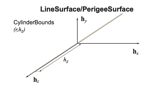
Line surface
Acts::LineSurface is a special kind of surface that depends on a reference
direction, typically the unit momentum direction \(\vec d\) of a particle. A point in
space is considered on surface if and only if it coincides with the point of
closest approach between the direction vector \(\vec d\) and the line direction
vector \(\vec z\). As such, the function Acts::LineSurface::globalToLocal()
can fail, if the argument position and direction do not fulfill this criterion.
It is pure-virtual, meaning that it can not be instantiated on its own.
-
class LineSurface : public Acts::Surface
Base class for a linear surfaces in the TrackingGeometry to describe dirft tube, straw like detectors or the Perigee It inherits from Surface.
Note
It leaves the type() method virtual, so it can not be instantiated
Subclassed by Acts::PerigeeSurface, Acts::StrawSurface
Public Functions
-
virtual Result<Vector2> globalToLocal(const GeometryContext &gctx, const Vector3 &position, const Vector3 &direction, double tolerance = s_onSurfaceTolerance) const final
Specified for
LineSurface: global to local method without dynamic memory allocation.This method is the true global -> local transformation. It makes use of
globalToLocaland indicates the sign of theActs::eBoundLoc0by the given momentum direction.The calculation of the sign of the radius (or \( d_0 \)) can be done as follows: May \( \vec d = \vec m - \vec c \) denote the difference between the center of the line and the global position of the measurement/predicted state. Then, \( \vec d \) lies in the so-called measurement plane. The latter is determined by the two orthogonal vectors \( \vec{\texttt{measY}} = \vec{e}_z \) and \( \vec{\texttt{measX}} = \vec{\texttt{measY}} \times \frac{\vec{p}}{|\vec{p}|} \).
The sign of the radius (or \( d_{0} \) ) is then defined by the projection of \( \vec{d} \) on \( \vec{measX} \):\( sign = -sign(\vec{d} \cdot \vec{measX}) \)
- Parameters
gctx – The current geometry context object, e.g. alignment
position – global 3D position - considered to be on surface but not inside bounds (check is done)
direction – global 3D momentum direction (optionally ignored)
tolerance – (unused)
- Returns
A
Result<Vector2>, which is set to!ok()if thepositionis not the point of closest approach to the line surface.
-
virtual SurfaceIntersection intersect(const GeometryContext &gctx, const Vector3 &position, const Vector3 &direction, const BoundaryCheck &bcheck = false, ActsScalar tolerance = s_onSurfaceTolerance) const final
Calculate the straight-line intersection with the line surface.
Mathematical motivation:
Given two lines in parameteric form:
\( \vec l_{a}(u) = \vec m_a + u \cdot \vec e_{a} \)
\( \vec l_{b}(\mu) = \vec m_b + \mu \cdot \vec e_{b} \)
The vector between any two points on the two lines is given by:
\( \vec s(u, \mu) = \vec l_{b} - l_{a} = \vec m_{ab} + \mu \cdot \vec e_{b} - u \cdot \vec e_{a} \),
where \( \vec m_{ab} = \vec m_{b} - \vec m_{a} \).
\( \vec s(u_0, \mu_0) \) denotes the vector between the two closest points
\( \vec l_{a,0} = l_{a}(u_0) \) and \( \vec l_{b,0} = l_{b}(\mu_0) \)
and is perpendicular to both, \( \vec e_{a} \) and \( \vec e_{b} \).
This results in a system of two linear equations:
(i) \( 0 = \vec s(u_0, \mu_0) \cdot \vec e_a = \vec m_{ab} \cdot \vec e_a + \mu_0 \vec e_a \cdot \vec e_b - u_0 \)
(ii) \( 0 = \vec s(u_0, \mu_0) \cdot \vec e_b = \vec m_{ab} \cdot \vec e_b + \mu_0 - u_0 \vec e_b \cdot \vec e_a \)
Solving (i) and (ii) for \( u \) and \( \mu_0 \) yields:
\( u_0 = \frac{(\vec m_{ab} \cdot \vec e_a)-(\vec m_{ab} \cdot \vec e_b)(\vec e_a \cdot \vec e_b)}{1-(\vec e_a \cdot \vec e_b)^2} \)
\( \mu_0 = - \frac{(\vec m_{ab} \cdot \vec e_b)-(\vec m_{ab} \cdot \vec e_a)(\vec e_a \cdot \vec e_b)}{1-(\vec e_a \cdot \vec e_b)^2} \)
The function checks if \( u_0 \simeq 0\) to check if the current
positionis at the point of closest approach, i.e. the intersection point, in which case it will return anonSuraceintersection result. Otherwise, the path length frompositionto the point of closest approach ( \( u_0 \)) is returned in areachableintersection.Note
expected to be normalized
- Parameters
gctx – The current geometry context object, e.g. alignment
position – The global position as a starting point
direction – The global direction at the starting point
bcheck – The boundary check directive for the estimate
tolerance – the tolerance used for the intersection
- Returns
is the intersection object
-
virtual Vector3 localToGlobal(const GeometryContext &gctx, const Vector2 &lposition, const Vector3 &direction) const final
Local to global transformation.
Note
for line surfaces the momentum direction is used in order to interpret the drift radius
- Parameters
gctx – The current geometry context object, e.g. alignment
lposition – is the local position to be transformed
direction – is the global momentum direction (used to sign the closest approach)
- Returns
global position by value
-
inline Vector3 normal(const GeometryContext &gctx) const
Normal vector return without argument.
-
virtual Vector3 normal(const GeometryContext &gctx, const Vector2 &lposition) const final
The normal vector is undefined if we do not know the momentum.
- Parameters
gctx – The current geometry context object, e.g. alignment
lposition – is the local position is ignored
- Returns
a zero vector
-
Vector3 normal(const GeometryContext &gctx, const Vector2 &lposition) const = 0
Normal vector return without argument.
-
Vector3 normal(const GeometryContext &gctx, const Vector3 &position) const
Normal vector return without argument.
-
virtual Result<Vector2> globalToLocal(const GeometryContext &gctx, const Vector3 &position, const Vector3 &direction, double tolerance = s_onSurfaceTolerance) const final
Straw surface
-
class StrawSurface : public Acts::LineSurface
Class for a StrawSurface in the TrackingGeometry to describe dirft tube and straw like detectors.
Perigee surface
-
class PerigeeSurface : public Acts::LineSurface
Class describing the Line to which the Perigee refers to.
The Surface axis is fixed to be the z-axis of the Tracking frame. It inherits from StraingLineSurface.
Layer classes
The Acts::Layer class is an extension of the Acts::Surface class that allows the
definition of sub surfaces (sensitive surfaces for modules, or extra material
surfaces).
The layer can simply correspond to a ‘virtual’ surface in the detector description or represent a more complex object that may contain:
a representing surface, which is accessible via a
Acts::Layer::surfaceRepresentation()an array of contained surfaces, accessible via
Acts::Layer::surfaceArray()methodapproach surfaces (i.e. boundary surface of the volume occupied by the layer)
surface material description on any of the confined surfaces
The following illustration shows an \(xy\) view of a cylinder layer with planar detection modules:
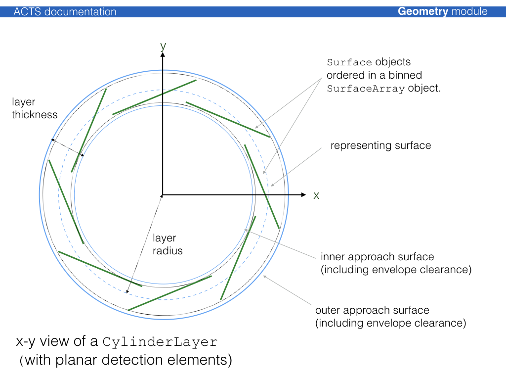
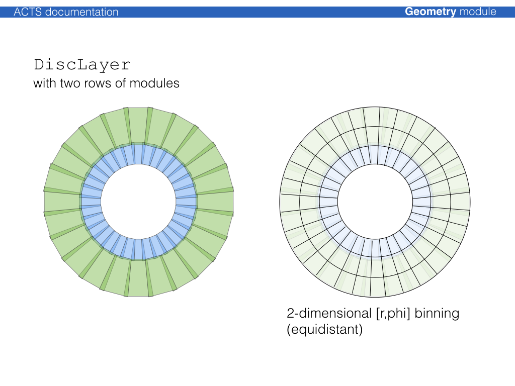
Modules can be sorted onto layer using all supported binning methods described
through the Acts::SurfaceArray class. The binning can be adjusted to fit as well as
possible.
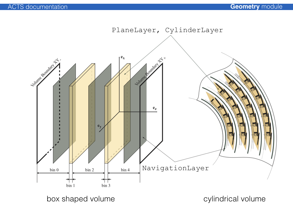
The unoccupied space in a volume that contains a layer array is filled with
objects of type Acts::NavigationLayer, which allows that in a fully static geometry
setup, every single point in a volume can be associated with a layer. Layer
objects are confined together in a special Acts::LayerArray class and can be
contained by a Acts::TrackingVolume.
Volume classes
The Acts::Volume class is a container of
Acts::BoundarySurface objects, where each
Acts::BoundarySurface is an extension of the Acts::Surface
class with additional information about the attached volumes. The normal vector
of the surface defines an inside (opposite w.r.t. the normal vector) and an
outside (along w.r.t. the normal vector) direction. Either a single volume or
an array of volumes can be attached to a volume.
The simples volume class is just a collection of surfaces, where the
Acts::TrackingVolume describes a volume that can contain:
an array of contained layers
an array of contained volumes (as a container volume)
an array of contained volumes (as floating objects)
a volume based material description
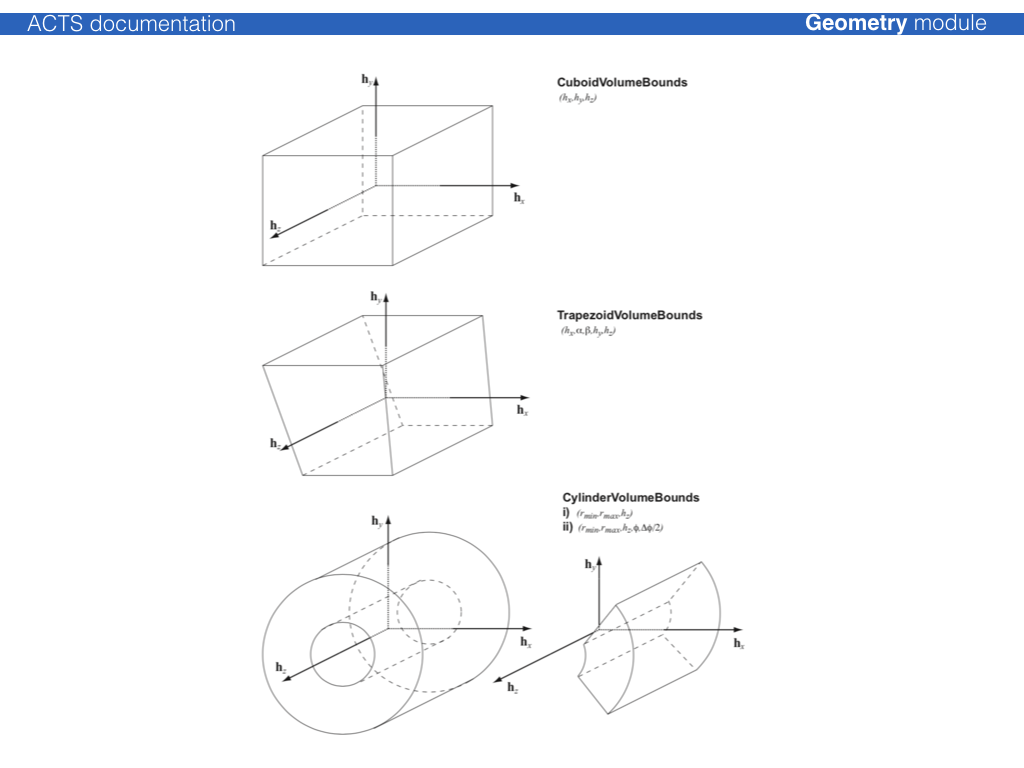
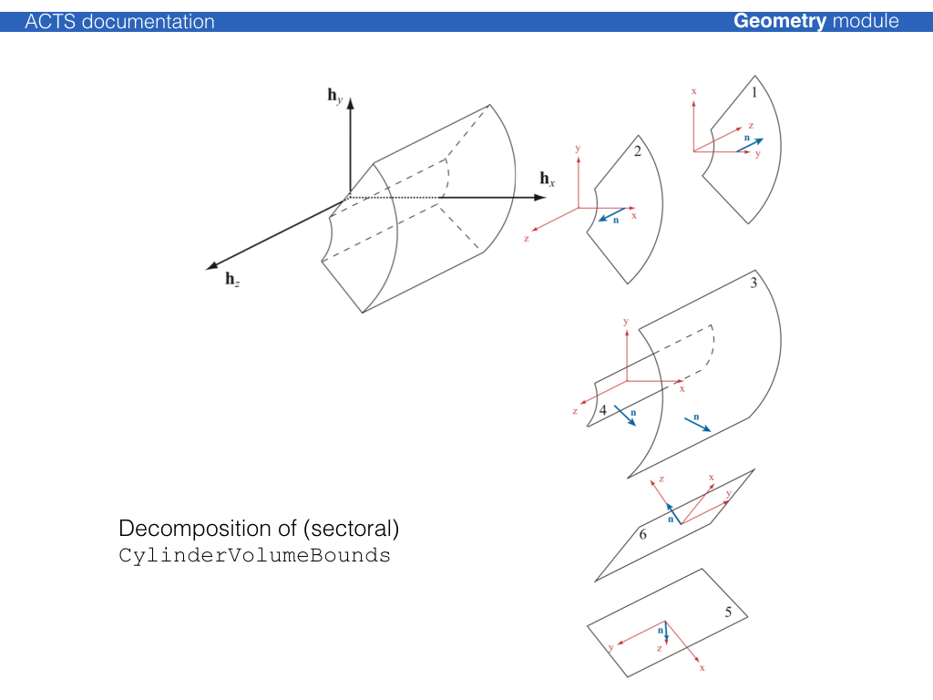
The shape of the volume is defined by Acts::VolumeBounds classes that create the
corresponding bounding surfaces and register the attachment to the volume itself
at creation.
Detector material description
Two types of material description exist, one for a surface based material, one for a volume based material. They will be dealt with differently in the extrapolation.
The basic information for any material is:
the radiation length X0 the nuclear interaction length L0 the atomic weight A
the atomic charge Z the density of the material
This information is confined together in the Acts::Material class.
Note
In track reconstruction, only an effective material description is needed, i.e. non-physical values in regards of the atomic number, the elementary charge or even the density are allowed, as long as the effective relative radiation length and \(A/Z \times \rho\) ratio can be retrieved. This enables the compactification of the material description, as the element composition record does not have to be kept.
Surface based material extends this material information by a representative
thickness; the corresponding object is called Acts::MaterialSlab. The
thickness hereby can be arbitrarily chosen in order to regulate the material
budget, it does not have to represent the actual thickness of a detector
element. To attach it to a surface, a dedicated Acts::SurfaceMaterial
class (or it’s extensions) is used, which allows to also describe binned
material.
Possible extensions are:
Acts::HomogeneousSurfaceMaterial, homogeneous material description on a surfaceActs::BinnedSurfaceMaterial, an arbitrarily binned material description with a correspondingActs::BinUtilityobject
In addition, a dedicated extension exists to allow configuration of the material mapping process, that is in further described below.
Acts::ProtoSurfaceMaterial, only binning description (without material) to be used in the material mapping process
Geometry building
The geometry building procedure follows the ATLAS tracking geometry philosophy of a static frame of glued volumes, that lead the navigation flow through the geometry,
Attaching a 3D detector geometry
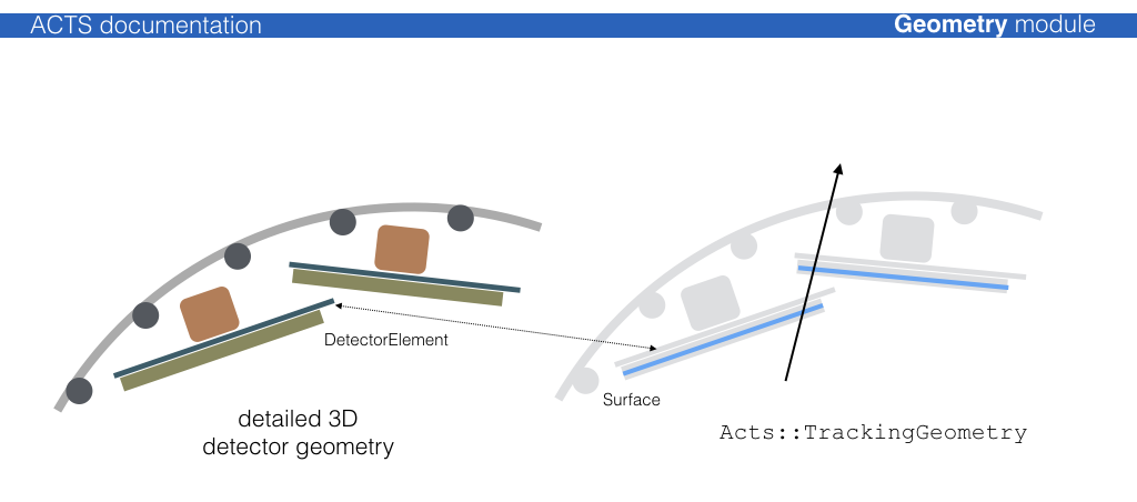
Usually, a 3D detector model geometry exists, which is either native to the full detector simulation (Geant4) or is translated into it. This model, however, is in general too detailed for track reconstruction: navigating through the detailed detector geometry is generally costly and one can profit greatly from a simplification mechanism.
For most part of the track reconstruction, only a surface based description of
the detector is needed, in order to allow (surface based) material integration
and parametrization/prediction of trajectories on detection surfaces. It is thus
necessary that the detection surfaces are described to full detail in the
reconstruction geometry (called Acts::TrackingGeometry). This is guaranteed by a
proxy mechanism that connects the detection elements (conveniently called
Acts::DetectorElement) to Acts::Surface object in the reconstruction:
Existing plugins for 3D geometry libraries
Very simple helper methods for 3D libraries exist, they are certainly not optimised, but used for templating:
Acts::TGeoDetectorElementconnects a TGeo volume to aActs::SurfaceActs::DD4HepDetectorElementconnects a DD4hep volume (based on TGeo) to aActs::SurfaceActs::Geant4DetectorElementconnects a Geant4 volume to aActs::Surface
Further extensions exist in dedicated experiment contexts, such as e.g. a GeoModel
binding for the ATLAS experiment.
Note
While DD4hep offers a descriptive language with a dedicated extension mechanism
that can be used by Acts to interpret the underlying geometry hierarchy and and structure,
there is no such guarantee when having the already as built TGeo geometry in hand.
Therefore a dedicated Acts configuration file based on json can be provided that allows
to specify parsing restrictions for sub detectors.
Layer building
Acts::Surface objects that are to be grouped on a layer should be put into a
Acts::SurfaceArray and provided to the layer. Certain helper tools exist to ease the
translation and create appropriate binning structure: The Acts::SurfaceArrayCreator
can create cylindrical, disc-like & planar layers, where the dimensions of the
layer are determined by parsing the provided surfaces. Additionally, an envelope
covering the surfaces can be chosen.
Note
There exist standard layer builders that are designed to build cylindrical, disk like
and planar layers and perform the ordering of the surfaces onto those layers. These
builders are called from the top level translation entry points from either TGeo
or DD4hep.
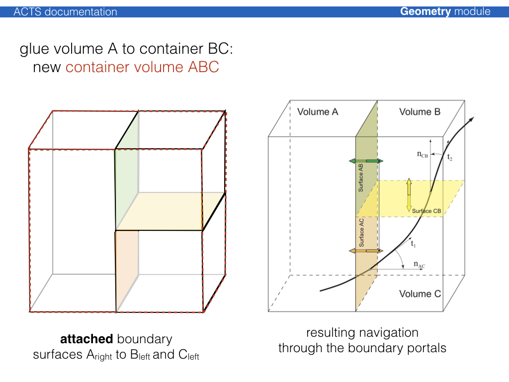
Volume building, packing, and gluing
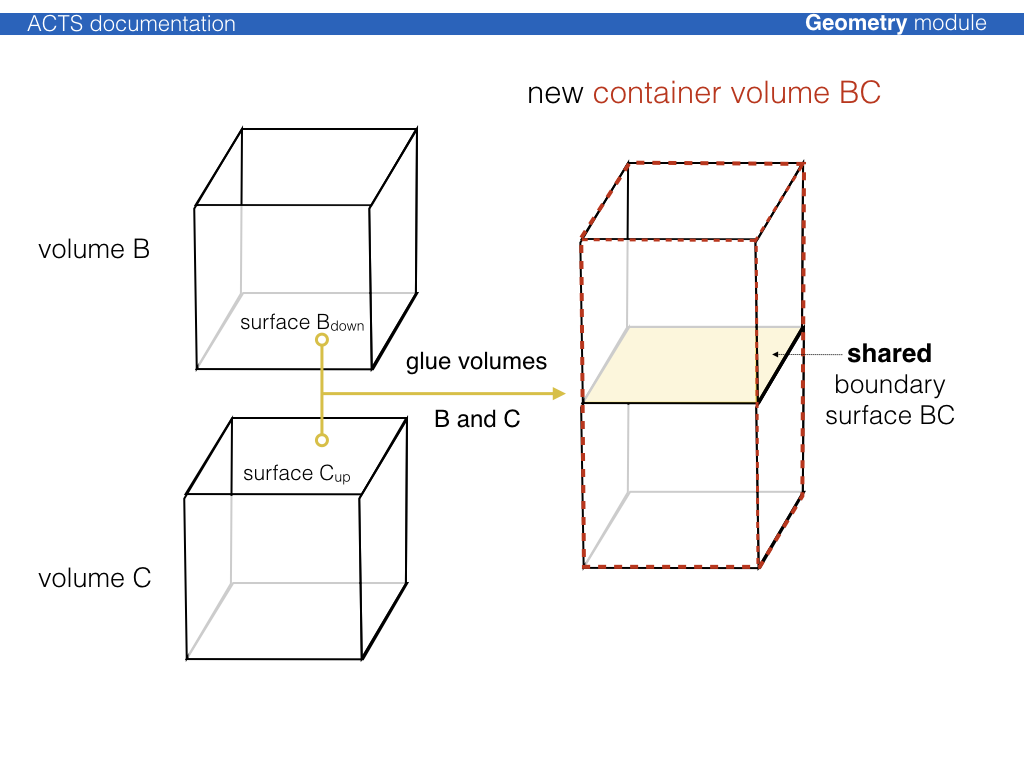
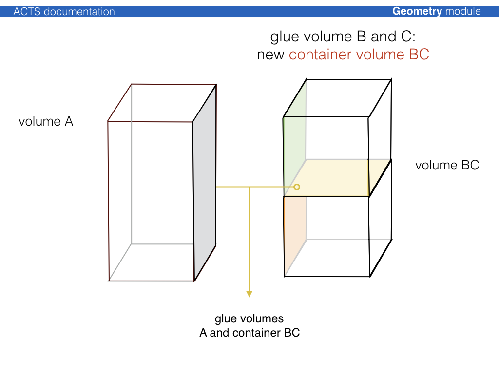
The philosophy of the Acts::TrackingGeometry is a fully connective geometry setup,
i.e. Acts::TrackingVolume objects are either pure containers for other contained
Acts::TrackingVolume instances (where the contained volumes fully fill the space of
the container volume), or are fully attached via the boundary surface mechanism.
The boundary surfaces then act as portals from one Acts::TrackingVolume into the
next one along the trajectory.
The process to create a fully connected tracking geometry is called glueing. Wherever possible, common boundary surfaces are shared, where this is not possible, they are attached.
For cylindrical detector setups, a dedicated Acts::CylinderVolumeBuilder is
provided, which performs a variety of volume building, packing and gluing.
Note
For most cylindrical detectors, there exist automated glueing and geometry building modules that take care of the glueing process.
TrackingGeometry building using a KDTree and a Proto Description
For cylindrical detectors there exist a generic tracking geometry building module, based on KDTree and a proto description.
This building procedure uses a Acts::ProtoDetector description which provides a
high level description of layers and container volumes, together with some
binning and ordering information.
This proto description is then used to assign surfaces that are provided to the
Acts::KDTreeTrackingGeometryBuilder using an internal query to the KD-tree structure.